- marketing-sales@tozen.com
- +6327 116 4865
- 0917 569 2698
- 0917 6271947
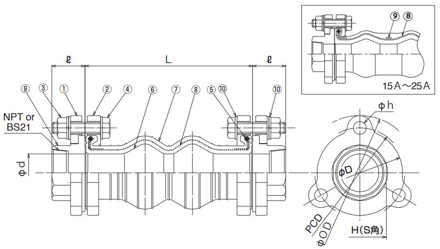
| No. | Parts | Material |
|---|---|---|
| 1 | Flange-A | Ductile Iron |
| 2 | Flange-B | Ductile Iron |
| 3 | Nut | Mild Steel |
| 4 | Bolt | Mild Steel |
| 5 | Reinforcing Cord | Synthetic Fiber |
| 6 | Inner Rubber | Synthetic Fiber |
| 7 | Outer Rubber | Synthetic Fiber |
| 8 | Reinforcing Cord | Synthetic Fiber |
| 9 | Union Edge | Ductile Iron |
| 10 | Washer | Mild Steel |
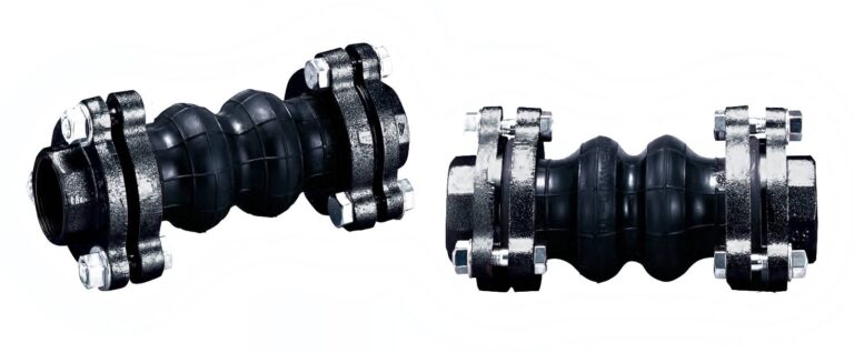
● The material of No.1, 2 & 9 can be changed to SUS304 and SUS316.
● The product is also applicable for oil use by changing the rubber material.
If need be, please contact us.
| Nominal Dia. | Dimension [mm] | Mass [Kg] | Union Edge [mm] | Flange [mm] | Allowable Movement [mm] | Installation Tolerances [mm] | |||||||||||||
|---|---|---|---|---|---|---|---|---|---|---|---|---|---|---|---|---|---|---|---|
| mm | inch | L | φd | ℓ | Rc | H | φD | PCD | φh | φOD | T.M. | A.E. | A.C. | A.M. | T.M. | A.E. | A.C. | A.M. | |
| 15 | 1/2 | 120 | 25 | 30 | 1.7 | 1/2 | 41 | 68 | 70 | 11.0 | 93 | 15 | 10 | 15 | 15 |
6 | 3 | 6 | 7.5 |
| 20 | 3/4 | 120 | 25 | 30 | 1.8 | 3/4 | 41 | 68 | 70 | 11.0 | 93 | 15 | 10 | 15 | 15 |
6 | 3 | 6 | 7.5 |
| 25 | 1 | 120 | 25 | 30 | 1.9 | 1 | 41 | 68 | 70 | 11.0 | 93 | 15 | 10 | 15 | 15 |
6 | 3 | 6 | 7.5 |
| 32 | 1 1/4 | 175 | 35 | 35 | 3.1 | 1 1/4 | 50 | 90 | 95 | 13.5 | 121 | 20 | 10 | 15 | 20 |
8 | 3 | 6 | 7.5 |
| 40 | 1 1/2 | 175 | 35 | 35 | 3.3 | 1 1/2 | 56 | 90 | 95 | 13.5 | 121 | 20 | 10 | 15 | 20 |
8 | 3 | 6 | 7.5 |
| 50 | 2 | 175 | 45 | 40 | 5.4 | 2 | 69 | 106 | 110 | 13.5 | 135 | 20 | 10 | 15 | 20 |
8 | 3 | 6 | 7.5 |
・A.C.: Axial Compression, A.E.: Axial Elongation,
A.M.: Angular Movement, T.M.: Transverse Movement
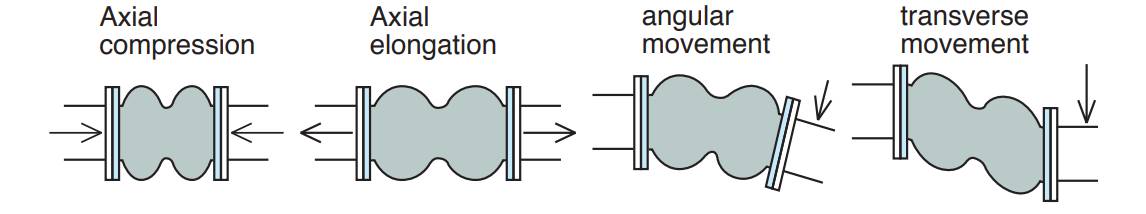
・Tolerances for installation are included in the allowable movements
(Allowable movements = Tolerances for installation + Operating movements).
・Please note that the information in the above table is for single movement only.
In case of complex movements, please do adjustment by using the following formula.
C.A.E. (C.A.C.) = A.A.E.(A.A.C.) × {1-(T.M / A.T.M. + A.M. /A.A.M)}
C.A.E. (C.A.C.): Correct Elongation Movement (Correct Compression Movement)
A.A.E. (A.A.C.): Allowable Elongation Movement (Allowable Compression Movement)
A.T.M.: Allowable Transverse Movement A.A.M.: Allowable Angular Movement
Example: In case of 50mm joint, if 10mm transverse movement is needed, then the correct elongation should be: C.A.E = 10 × {1- (10/20 + 0/20)} = 5mm
・There is reaction force from rubber joints due to the load of the internal pressure, so during the installation, please use the metal fittings to fix the pipe tightly to ensure the joints work efficiently. In case the pipe cannot be fixed tightly, please use the control unit for the joints.
Note: The content of this catalog is subject to change without prior notice.