- marketing-sales@tozen.com
- +6327 116 4865
- 0917 569 2698
- 0917 6271947
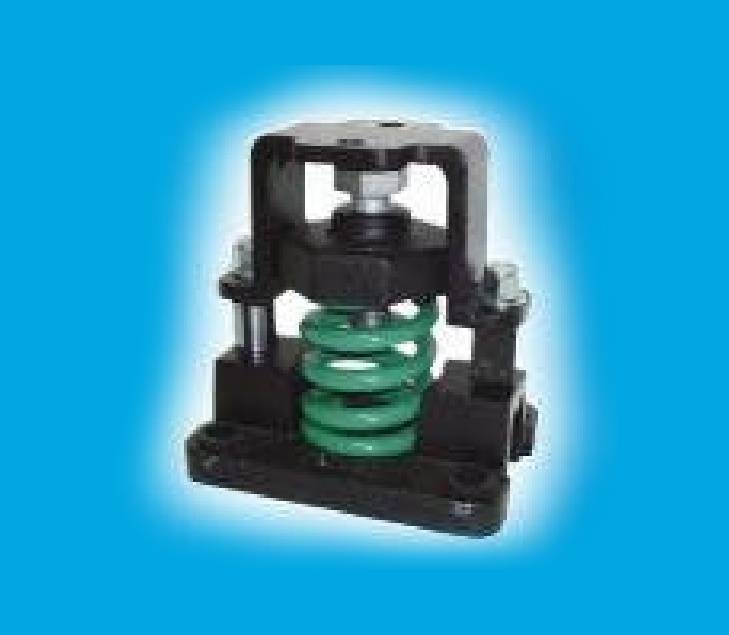
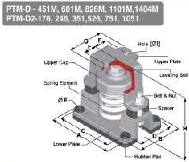
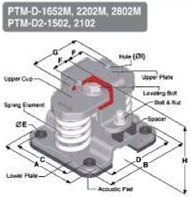
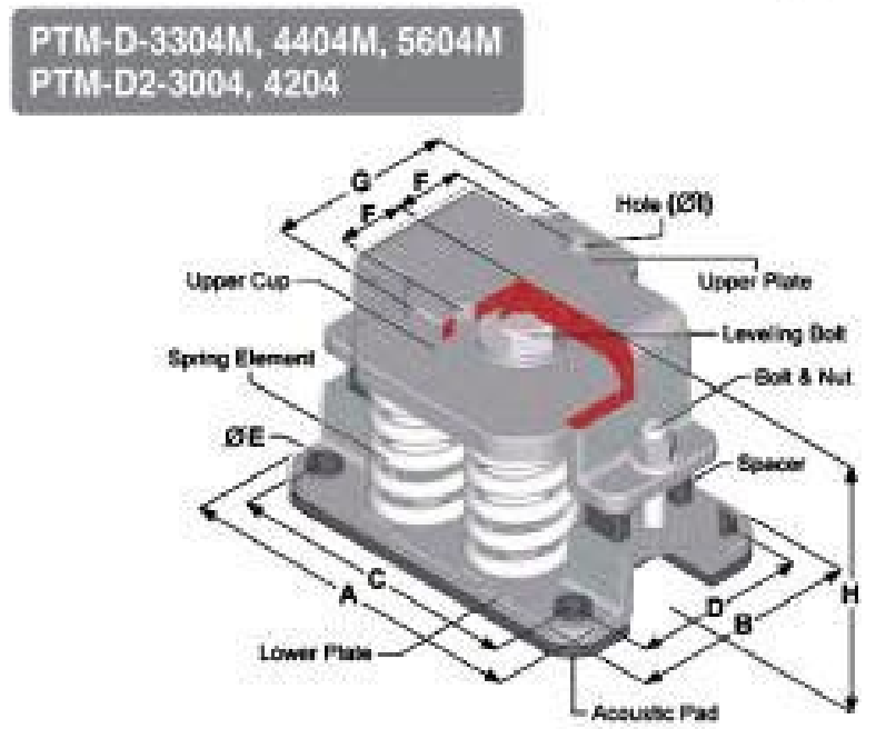
PTM-D TYPE
25mm DEFLECTION RESTRAINED SPRING ISOLATOR
| MODEL | RATED CAPACITY | SPRING CONSTANT (kgs/mm) |
SPRING COLOR | OPERATING HEIGHT (H) |
DIMENSION (MM) | ||||||||
|---|---|---|---|---|---|---|---|---|---|---|---|---|---|
| (kgs) | (Lbs) | A | B | C | D | ØE | F | G | ØI | ||||
| PTM-D-450M | 450 | 990 | 18 | GREEN | 170 | 172 | 121 | 137 | 86 | 16 | 30 | 88 | 14 |
| PTM-D-601M | 600 | 1320 | 24 | SILVER | |||||||||
| PTM-D-826M | 825 | 1815 | 33 | BROWN | |||||||||
| PTM-D-1101M | 1100 | 2420 | 44 | BLUE | |||||||||
| PTM-D-1401M | 1400 | 3080 | 56 | BLUE+BROWN | |||||||||
| PTM-D-1652M | 1650 | 3630 | 66 | BROWN | 170 | 180 | 200 | 136 | 156 | 20 | 40 | 118 | 18 |
| PTM-D-2202M | 2200 | 4540 | 88 | BLUE | |||||||||
| PTM-D-2802M | 2800 | 6160 | 112 | BLUE+BROWN | |||||||||
| PTM-D-3304M | 3300 | 7260 | 132 | BROWN | 185 | 255 | 167 | 211 | 1235 | 20 | 48.5 | 135 | 18 |
| PTM-D-4404M | 4400 | 9680 | 176 | BLUE | |||||||||
| PTM-D-5604M | 5600 | 12320 | 224 | BLUE+BROWN |
NOTE-1: All springs are free standing and laterally stable. (Outside diameter do not less 0.8 times of compressed height)
NOTE-2: All springs are designed to provide additional travel to solid of at least 50 rated load.
NOTE-3: Please refer to relevant brochure or factory for greater deflection and loading
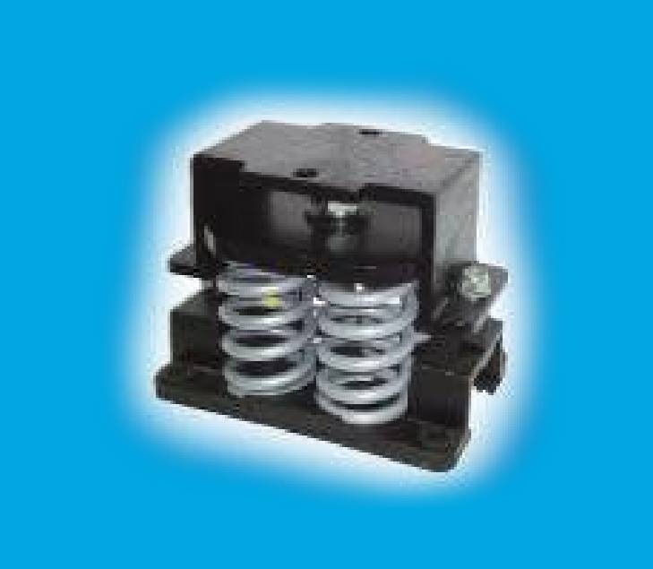
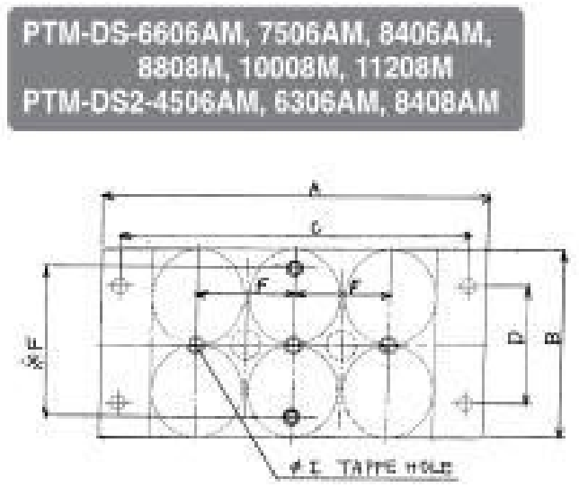
PTM-DS TYPE
25mm DEFLECTION RESTRAINED SPRING ISOLATOR
| MODEL | RATED CAPACITY | SPRING CONSTANT (kgs/mm) |
SPRING COLOR | OPERATING HEIGHT (H) |
DIMENSION (MM) | ||||||||
|---|---|---|---|---|---|---|---|---|---|---|---|---|---|
| (kgs) | (Lbs) | A | B | C | D | ØE | F | G | ØI | ||||
| PTM-DS-4956MA | 4950 | 10890 | 198 | BROWN | 205 | 420 | 175 | 380 | 100 | 20 | 110 | – | M16x3 |
| PTM-DS-6606MA | 6600 | 14520 | 264 | BLUE | |||||||||
| PTM-DS-7506MA | 7500 | 16500 | 300 | BLUE+WHITE | |||||||||
| PTM-DS-8406MA | 8400 | 18480 | 335 | BLUE+BROWN | |||||||||
| PTM-DS-8808MA | 8800 | 19360 | 352 | BLUE | 205 | 475 | 175 | 435 | 100 | 20 | 115 (ØF |
– | M16x2 |
| PTM-DS-10008MA | 10000 | 22000 | 400 | BLUE+WHITE | |||||||||
| PTM-DS-11208MA | 11200 | 24640 | 448 | BLUE+BROWN |
NOTE-1: All springs are free standing and laterally stable. (Outside diameter do not less 0.8 times of compressed height)
NOTE-2: All springs are designed to provide additional travel to solid of at least 50 rated load.
NOTE-3: Please refer to relevant brochure or factory for greater deflection and loading
NOTE-4: PTM-DS is carbon steel type
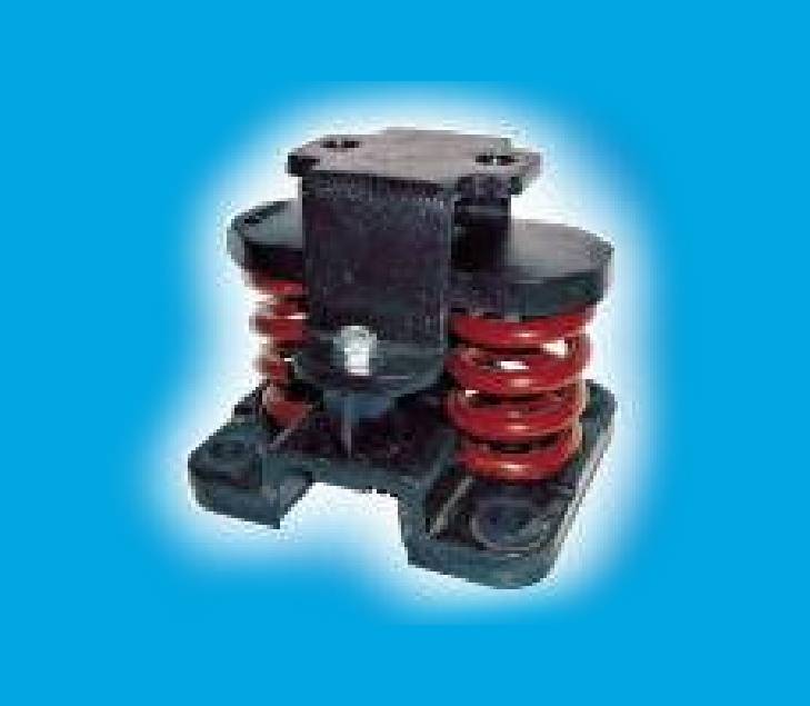
PTM-D2 TYPE
50mm DEFLECTION RESTRAINED SPRING ISOLATOR
| MODEL | RATED CAPACITY | SPRING CONSTANT (kgs/mm) |
SPRING COLOR | OPERATING HEIGHT (H) |
DIMENSION (MM) | ||||||||
|---|---|---|---|---|---|---|---|---|---|---|---|---|---|
| (kgs) | (Lbs) | A | B | C | D | ØE | F | G | ØI | ||||
| PTM-D2-176 | 175 | 385 | 3.5 | ORANGE | 210 | 190 | 130 | 152 | 95 | 16 | 38 | 106 | 16 |
| PTM-D2-246 | 245 | 539 | 4.9 | VIOLET | |||||||||
| PTM-D2-351 | 350 | 770 | 7 | RED | |||||||||
| PTM-D2-526 | 525 | 1155 | 10.5 | GREEN | |||||||||
| PTM-D2-751 | 750 | 1650 | 15 | SILVER | |||||||||
| PTM-D2-1051 | 1050 | 2310 | 21 | SILVER+BROWN | 210 | 232 | 196 | 187 | 152 | 20 | 42 | 120 | 16 |
| PTM-D2-1502 | 1500 | 3300 | 30 | SILVER | |||||||||
| PTM-D2-2102 | 2100 | 4620 | 42 | SILVER+BROWN | |||||||||
| PTM-D2-3004 | 3000 | 600 | 60 | SILVER | 220 | 300 | 200 | 250 | 162 | 20 | 66.5 | 170 | 20 |
| PTM-D2-4204 | 4200 | 9240 | 84 | SILVER+BROWN |
NOTE-1: All springs are free standing and laterally stable. (Outside diameter do not less 0.8 times of compressed height)
NOTE-2: All springs are designed to provide additional travel to solid of at least 50 rated load.
NOTE-3: Please refer to relevant brochure or factory for greater deflection and loading
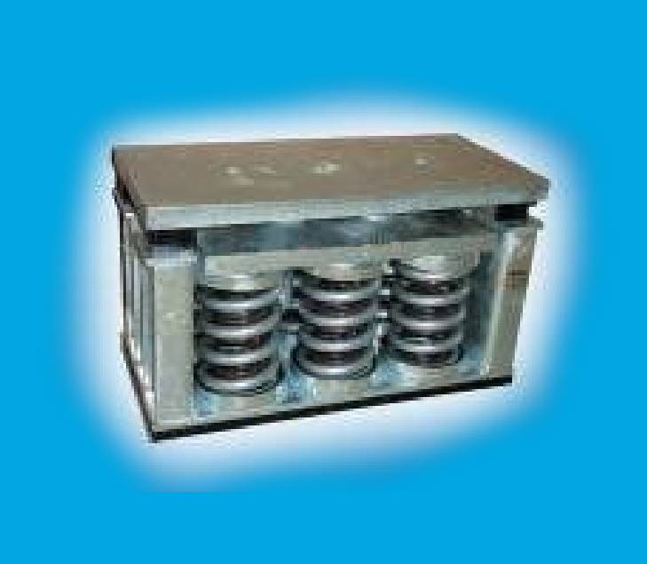
PTM-DS2 TYPE
50mm DEFLECTION RESTRAINED SPRING ISOLATOR
| MODEL | RATED CAPACITY | SPRING CONSTANT (kgs/mm) |
SPRING COLOR | OPERATING HEIGHT (H) |
DIMENSION (MM) | ||||||||
|---|---|---|---|---|---|---|---|---|---|---|---|---|---|
| (kgs) | (Lbs) | A | B | C | D | ØE | F | G | ØI | ||||
| PTM-DS2-4506MA | 4500 | 9900 | 90 | SILVER | 250 | 430 | 207 | 390 | 132 | 20 | 110 | – | M16X3 |
| PTM-DS2-6306MA | 6300 | 13860 | 126 | SILVER+BROWN | |||||||||
| PTM-DS2-8408MA | 8400 | 18480 | 168 | SILVER+BROWN | 250 | 540 | 207 | 500 | 132 | 20 | 147 (ØF) |
– | M16X3 |
NOTE-1: All springs are free standing and laterally stable. (Outside diameter do not less 0.8 times of compressed height)
NOTE-2: All springs are designed to provide additional travel to solid of at least 50 rated load.
NOTE-3: Please refer to relevant brochure or factory for greater deflection and loading
NOTE-4: PTM-DS is carbon steel type