Design and test standard:
ASSE 3001 Water Pressure Reducing Valves for Domestic Water Distribution Systems
EN1567 Water pressure reducing valves and combination water reducing valves-Requirements and tests
•Balanced Design
•Bigger diaphragm and react more sensitive
•Special design “yoke” stem, avoiding block
•Install and operation in any position
•Easy installation and maintenance
| Size: | 3/8”–2” |
| Type: | Direct Acting |
| Connection: | PT/NPT |
| Material: | SUS 304/316/ Bronze |
| Media: | Pure water |
| Working temperature: | 0-80 ºC |
| Pressure range: | PN16 |
The Model K200S Pressure Reducing Valve automatically reduces a higher inlet pressure to a steady lower downstream pressure, regardless of changing flow rate and/or varying inlet pressure.
This valve is an accurate regulator capable of holding downstream pressure to a re-determined limit. When downstream pressure exceeds the pressure setting , the valve close drip-tight.
Why use a Direct Acting Pressure Reducing Valve D200
Because of growth, we are faced, more and more, with the challenge to protect our environment. Conserving our energy and water supply is one of the most important aspects of this global challenge. Since we can not increase our supply, we must re duce our consumption. After years of carelessness, we have finally recognized the need for a more responsible pattern of water use. Fortunately there is a simple solution to reducing consumption without changing our lifestyles.
D200 is an automatic control which is in stalled at the water meter in homes to reduce the city main pressure to a lower, more functional pressure. When the water pressure is reduced, less water is used . If these saving were applied to a million homes, consider the impact this would have on our consumption goals. D200 is equally effective for use in commercial buildings and irrigation systems.
Not only is installing a D200 valve good for the environment, it saves money as well. Excessive water pressure can be harmful to a home plumbing system, causing damage to pipes, faucets, and appliances. Regulators increase the life span of dish washers and water heaters and reduce the noise of banging pipes caused by the “water hammer” effect.

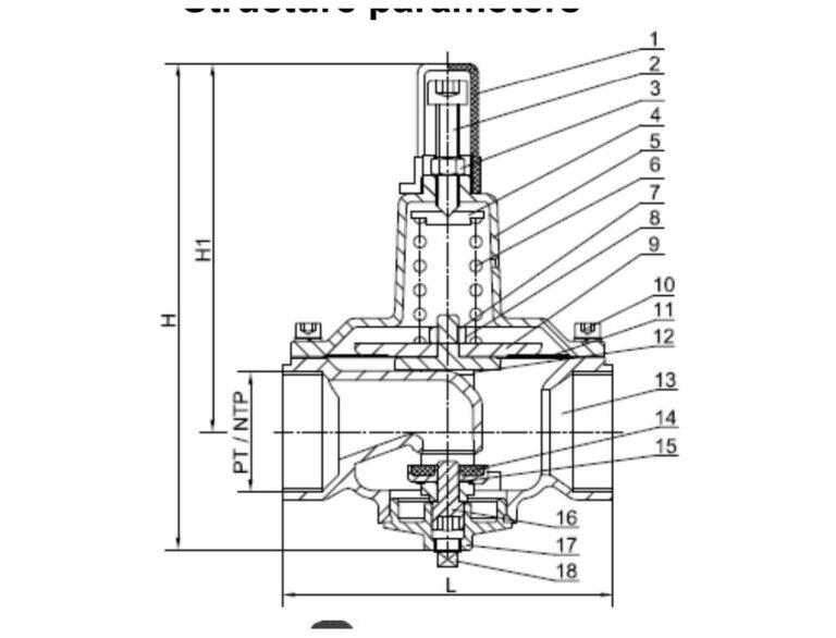
| Inch | DN | L | H | H1 |
|---|---|---|---|---|
| 3//8 | 10 | 80 | 175 | 133 |
| 1//2 | 15 | 97 | 168 | 128 |
| 3//4 | 20 | 100 | 178 | 135 |
| 1 | 25 | 106 | 183 | 139 |
| 1 1//4 | 32 | 112 | 188 | 143 |
| 1 1//2 | 40 | 124 | 190 | 144 |
| 2 | 50 | 170 | 216 | 164 |
Notice:
If want flange connection, then the flanges will be weld to both inlet and outlet of body


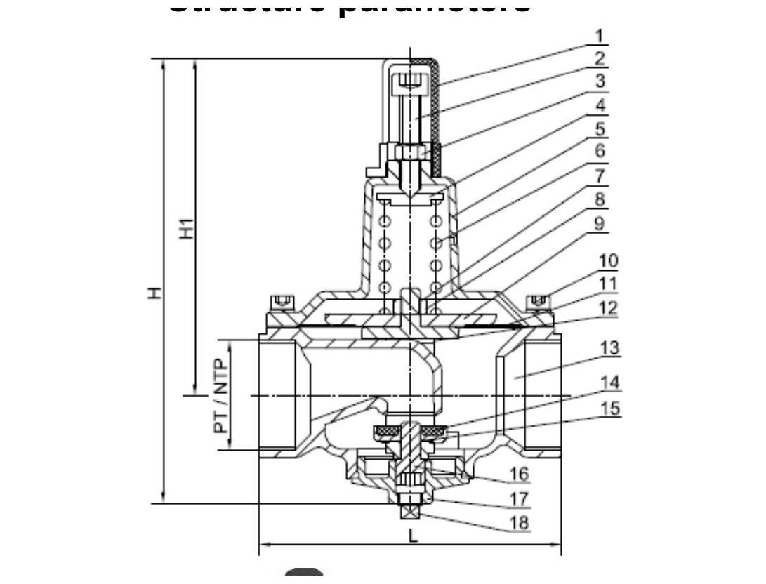
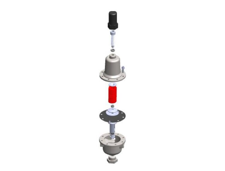
| NO. | Part Name | Standard | Option1 | Option2 |
|---|---|---|---|---|
| 1 | Cap | ABS | ||
| 2 | Adjusting Crew | SUS304 | SUS316 | SUS31 6L |
| 3 | Jam Nut | A2 | A4 | |
| 4 | Spring Guide | SUS304 | SUS316 | SUS31 6L |
| 5 | Bonnet | SUS304 | SUS316 | SUS31 6L |
| 6 | Spring | Cr-VA | ||
| 7 | Nut | A2 | A4 | |
| 8 | Washer | A2 | A4 | |
| 9 | Fixing Holder | SUS304 | SUS316 | SUS31 6L |
| 10 | Screw | A2 | A4 | |
| 11 | Diaphragm | NBR + Nylon | ||
| 12 | Yoke | SUS304 | SUS316 | SUS31 6L |
| 13 | Body | SUS304 | SUS316 | SUS31 6L |
| 14 | Disc | SUS304 + EPDM | SUS316 + EPDM | SUS31 6L + EPDM |
| 15 | O-Ring | NBR | ||
| 16 | Spindle | SUS304 | SUS316 | SUS31 6L |
| 17 | Cover | SUS304 | SUS316 | SUS31 6L |
| 18 | Plug | SUS304 | SUS316 | SUS31 6L |
Notice:
If want other material, please consult factory
INSTALLATION
D200 may be installed in any position.
OPERATION
D200 is normally held open by the force of the compression spring above the diaphragm; and delivery pressure acts on the underside of the diaphragm. Flow through the valve responds to changes in downstream demand to maintain a pressure.
ADJUSTMENT PROCEDURE
D200 can be adjusted to provide a delivery pressure range as customer needed, Pressure adjustment is made by turning the adjustment screw to vary the spring pressure on the diaphragm. The greater the compression on the spring the higher the pressure setting.
1. Turn the adjustment screw in (clockwise) to increase delivery pressure.
2. Turn the adjustment screw out (counter-clockwise) to decrease the delivery pressure.
3. When pressure adjustment is completed, tighten jam nut on adjusting screw and replace protective cap.
MAINTENANCE
Disassembly
Unscrew 1#cap, 2#adjusting screw;
Unscrew 10# bolts and remove 5#bonnet;
Remove 4#Spring guide and 6#spring;
Turn out 17# plug;
Turn out 16# spindle and 14#disc with inner hexagon spanner; and check the rubber seal
in disc, if it fails, replace with a new one.
Unscrew 7#nut , and check the 11# diaphragm, if it fails, replace with a new one.
Take the 12#yoke off body;
Reassembly
Reassembly is the reverse of disassembly. Caution: must be taken to avoid having the yoke drag on the inlet nozzle of the Body
Trouble shooting
See table left
| SYMPTOM | PROBABLE CAUSE | REMEDY |
|---|---|---|
| Fails to open when deliver pressure lowers | No spring compression | Tighten adjusting screw |
| Damaged spring | Disassemble and replace | |
| Spring guide is not in position | Assemble properly | |
| Yoke dragging on inlet nozzle | Disassemble and reassemble properly | |
| Fails to close when delivery pressure rises | Spring compressed solid | Back off adjusting screw |
| Mechanical obstruction | Disassemble and reassemble properly | |
| Worn disc | Disassemble remove and replace disc retainer assembly | |
| Yoke dragging on inlet nozzle | Disassemble and reassemble properly | |
| Leakage from cover vent hole | Damaged diaphragm | Disassemble and replace |
| Loose diaphragm nut | Remove cover and tighten nut |