- marketing-sales@tozen.com
- +6327 116 4865
- 0917 569 2698
- 0917 6271947
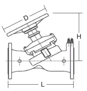
| Size (mm) |
L (mm) |
H (mm) |
D (mm) |
Weight (kg) |
Kvs |
|---|---|---|---|---|---|
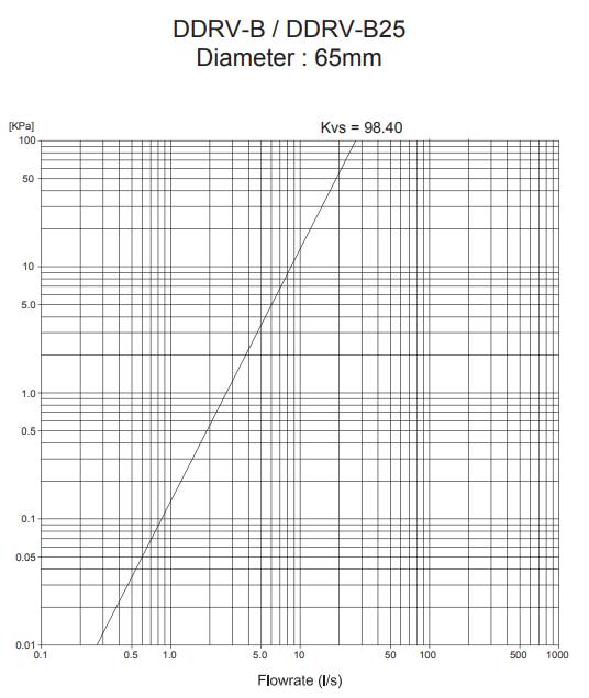
| 65 | 290 | 265 | 200 | 17 | 98.40 |
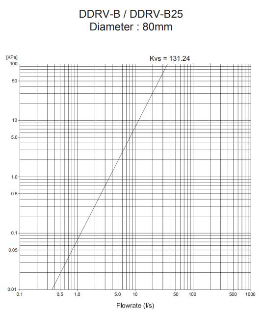
| 80 | 310 | 270 | 200 | 20 | 131.24 |
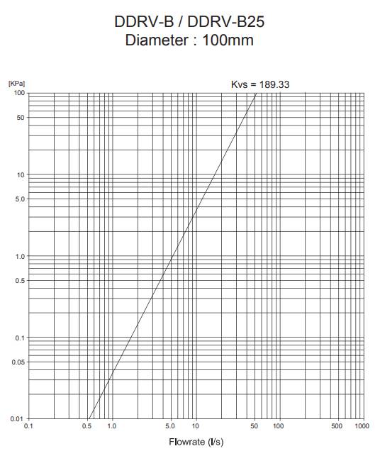
| 100 | 350 | 310 | 240 | 29 | 189.33 |
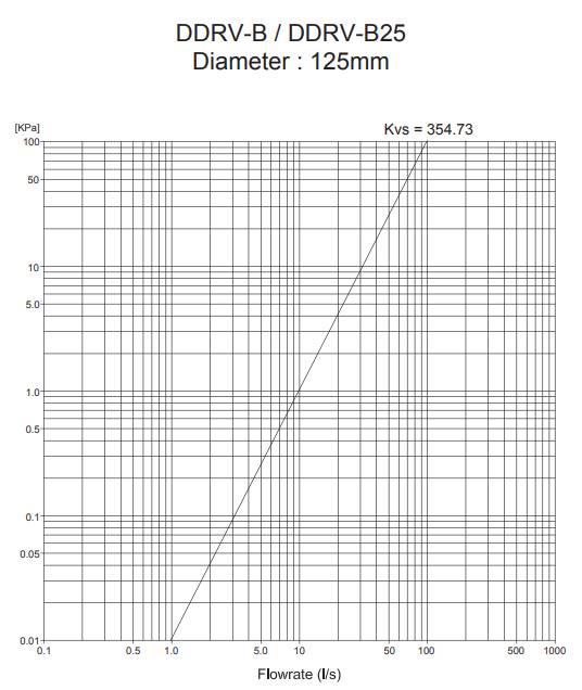
| 125 | 400 | 340 | 290 | 40 | 354.73 |
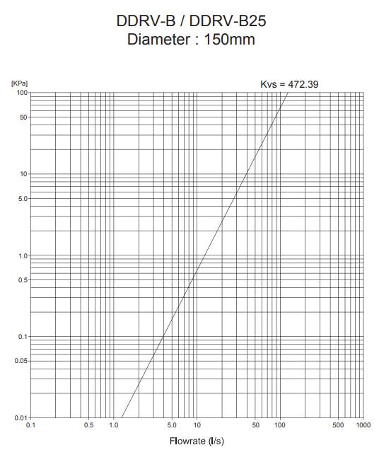
| 150 | 480 | 340 | 290 | 52 | 472.39 |
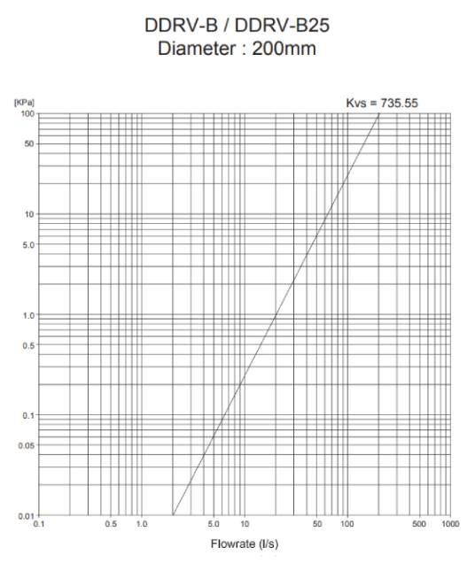
| 200 | 600 | 537 | 350 | 113 | 735.55 |
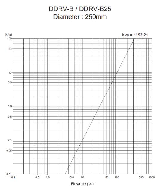
| 250 | 730 | 570 | 420 | 185 | 1153.21 |
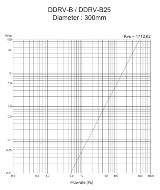
| 300 | 850 | 690 | 420 | 248 | 1712.62 |
Note: Kvs at fully open position.
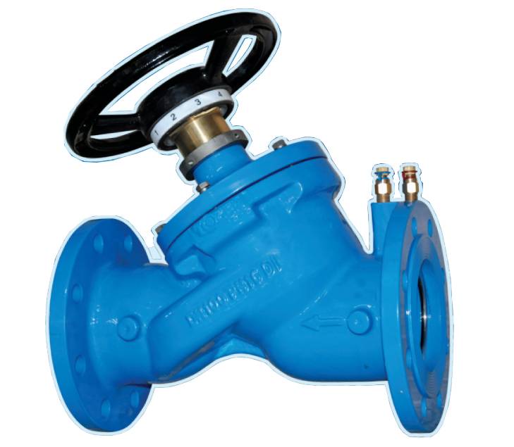
• The Double Regulating Valve shall be installed with the arrow marking on the valve body in accord to the same flow direction in the pipe. It may be installed at any angle.
• The gasket must be assembled between the flanges when the valve is installed. It can ensure that the valve is concentric with the pipe and the exact measurement data can be read.
• Avoid welding with pipe while it is connected. Tighten flanges bolts alternately, diagonally and repeatedly with the same force.
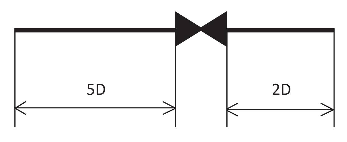
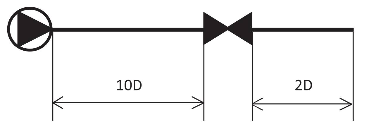
• Up and down stream from the valve is required to avoid turbulence which will affect the accuracy.